Dynamic Resolution Rendering (Intel)
http://software.intel.com/en-us/articles/dynamic-resolution-rendering-article/
Tuesday, October 11, 2011
Friday, October 7, 2011
Reflection
Good post on C++ reflection systems:
http://altdevblogaday.com/2011/09/25/reflection-in-c-part-1-introduction/
http://altdevblogaday.com/2011/09/25/reflection-in-c-part-1-introduction/
Thursday, August 11, 2011
DirectX 11 : BC6H and BC7 Texture Compression
DirectX 11 includes these new high quality texture compression formats. The DX SDK has samples with compute shader implementations of compressors and decompressors of the new formats.
Good technical info on the formats:
BC6H
http://msdn.microsoft.com/en-us/library/windows/desktop/hh308952%28v=vs.85%29.aspx
BC7
http://msdn.microsoft.com/en-us/library/windows/desktop/hh308953%28v=vs.85%29.aspx
More details are available in the OpenGL spec:
http://www.opengl.org/registry/specs/ARB/texture_compression_bptc.txt
This presentation also includes some information on the new formats which are basically new interpolation methods:
http://www.nvidia.com/content/nvision2008/tech_presentations/Game_Developer_Track/NVISION08-Direct3D_11_Overview.pdf
BC6H - floating point data
High Dynamic Range
6:1 Compression (16 bpc RGB)
BC7 - 8-bit fixed point data
LDR with alpha
3:1 compression for RGB or 4:1 for RGBA
Comparison of the formats
http://www.g-truc.net/post-0340.html
DirectX 11 : Compute Shaders
Resources on learning about Compute Shaders
This is an important presentation on the performance characteristics of compute shaders and things to look out for. Compute shaders are not necessarily faster than PS and CS settings need to be tuned for optimal performance on different GPUs.
http://developer.amd.com/gpu_assets/DirectCompute%20Performance.zip
This page has some good links:
http://www.danielmoth.com/Blog/DirectCompute.aspx
Good info on Compute Shader thread specifics and how they relate to real hardware:
http://developer.amd.com/gpu_assets/Efficient%20Compute%20Shader%20Programming.pps
http://openvidia.sourceforge.net/index.php/DirectCompute
Compute Shader Debugging
http://cmpmedia.vo.llnwd.net/o1/vault/gdc10/slides/Aguaviva_Raul_OptimizingGraphicsApplicationsWithAMDGPUPerfStudio2.pdf
Nvidia Parallel Reductions with CUDA (Compute Shaders)
http://developer.download.nvidia.com/compute/cuda/1_1/Website/projects/reduction/doc/reduction.pdf
Wednesday, July 13, 2011
Videogame Programmer Interviews
Just a collection of references on programming interview questions and techniques.
http://www.kreationsedge.com/?p=76
http://maxnoy.com/interviews.html
http://www.kreationsedge.com/?p=76
http://maxnoy.com/interviews.html
Friday, June 10, 2011
Lock Free Algorithm Research
Good intro to lock-free programming:
https://github.com/boostcon/2010.../raw/.../lockfree_boostcon2010.pdf
Herb Sutter's Articles on Lock-Free Algorithms and Data Structures
Effective Concurrency: Lock Free Code - A False Sense of Security
http://drdobbs.com/cpp/210600279
Writing a Generalized Concurrent Queue
http://drdobbs.com/high-performance-computing/211601363
For more:
http://herbsutter.com
www.cs.rochester.edu/~scott/papers/1996_PODC_queues.pdf
http://www.cs.rochester.edu/research/synchronization/pseudocode/queues.html
Friday, April 29, 2011
Global Illumination Research
Lionhead Studio's GI System
http://www.gdcvault.com/play/1014350/Mega-Meshes-Modeling-Rendering-and
The technique here is similar to Bunnell's but the presentation is a bit confusing even though the idea is simple.
Offline Stage
1) Generate lighting probes. Light probes are generated for the surface of static objects and for irradiance volume sample points for dynamic objects. A light probe just stores the set of "surface probes" that it can see which is calculated via raycasts.
2) Generate surface probes. Random points on geometry, then optimized.
3) Compute visibility. This is where the set of surface points visible to each light probe is computed.
4) Create SH vector palette.
Online Stage
1) Calculate direct illumination for surface probes.
2) Propagate lighting to lighting probes.
----------------------------------------------------
Geomerics Enlighten
http://www.geomerics.com/downloads/radiosity_architecture.pdf
DirectX 11 Tessellation Notes
Good tutorial and introduction to programming the DirectX11 tessellator
http://www.geeks3d.com/20101126/direct3d-11-tessellation-tutorial/
Hull Shader Stage
This stage is divided into two parts, ConstantHS and MainHS.
ConstantHS is invoked once per primitive and it's function is to output the Tessellation Factor.
MainHS is invoked per control point and it's purpose is to calculate any basis change on the primitive.
Tessellator Unit
Tessellator outputs up to 8192 triangles per input patch. The exact triangle amount is passed as a parameter.
This stage creates new triangles that compose a regular grid with texture coordinates ranging from 0 to 1.
Tessellation can be achieved in 3 different ways: integer, even-fractional, odd-fractional. Integer is a straightforward symmetric subdivision. The fractional versions subdivide the edges and interpolate between different lod levels for a smoother transition.
Domain Shader Stage
The domain shader is invoked once per vertex output from the tessellator and it's role is to compute the parametric position based on the control points from the hull shader. This is also where displacement maps would be applied.
Thursday, April 28, 2011
DirectX 11 Overview Notes
A paper on the DirectX10 design decisions and the rationale for those decisions
http://download.microsoft.com/download/f/2/d/f2d5ee2c-b7ba-4cd0-9686-b6508b5479a1/direct3d10_web.pdf
Details on Migrating from D3D9 to D3D11
http://msdn.microsoft.com/en-us/library/ff476190.aspx
Good General Overview of the Direct3D11 Systems
http://developer.download.nvidia.com/presentations/2008/NVISION/NVISION08_Direct3D_11_Overview.pdf
DirectX11 is not supported on Windows XP. This forum explains why:
http://www.gamedev.net/topic/552391-having-support-for-dx9--dx10--dx11/
Resources for Porting DirectX9 to DirectX11
http://developer.amd.com/assets/Riguer-DX10_tips_and_tricks_for_print.pdf
http://developer.amd.com/documentation/articles/pages/7112007172.aspx
http://msdn.microsoft.com/en-us/library/bb205073%28v=vs.85%29.aspx
New Features
Shader Model 5
Compute Shader
Dynamic Shader Linkage
Multi-threading - multi-threaded resource creation and command buffer creation
Tesselation
Computer Shader - New Resource Types
Shader Model 5 introduces a new set of read/write resources.
RWBuffer
RWTexture1D, RWTexture1DArray
RWTexture2D, RWTexture2DArray
RWTexture3D
These resources require a resource variable to access memory as there are no methods for accessing memory directly.
Structured Buffers
Structured buffers are arrays of structures defined by the user.
StructuredBuffer
RWStructuredBuffer
Atomic Functions which implement interlocked operations are allowed on int and uint elements of RWStructuredBuffer.
Byte Address Buffer
ByteAddressBuffer
RWByteAddressBuffer
Are buffers addressed by 4-byte aligned byte offsets.
Unordered Access Buffer or Texture
An unordered access resource (which includes buffers, textures and texture arrays - without multisampling) allows temporally unordered read/write access from multiple threads. Conflicts are avoided using atomic functions.
Use the D3D11_BIND_UNORDERED_ACCESS flag from D3D11_BIND_FLAG when creating buffers or texture2D resources.
These resources can only be bound to pixel and compute shaders.
Append and Consume Buffer
These buffers provide a queue like functionality where the append buffer is the input and the consume is the output.
AppendStructuredBuffer
ConsumeStructuredBuffer
Atomic Functions
Atomic functions are used to access the new resources types and shared memory from compute shaders.
Compute shaders are created with the new ID3D11Device::CreateComputeShader function call.
Direct3D 11 Devices
Device can be run in immediate or deferred mode. Deferred mode is only needed for multi-threaded applications.
Direct3D 11 Resources
D3D11 introduces a more generalized model of resources. Resources represent memory accessors/views of various types. They can be specified as typed, typeless, read, write, read/write, CPU, GPU, CPU/GPU. Up to 128 resources can be addressed by each pipeline stage at any time.
Typeless resources don't specify a specific type (eg: int, sint, float, srgb) but they do specify the number of bits allocated to each color component.
Resource Views are used to interpret typeless resources as a particular type. Conceptually, they are similar to casting (interpreting) a memory address in C/C++. The resource view must have the same allocation of bits to each color component as the typeless resource (eg: a R8G8B8A8 resource view can only be used for R8G8B8A8 typeless resources).
A resource view also exposes capabilities like reading back depth/stencil surfaces in a shader, rendering a dynamic cube map in a single pass and rendering simultaneously to multiple slices in a volume texture.
Subresources
Subresources are used to represent individual pieces of a resource. For example, the mip levels of a texture are all subresources that can be addressed in shaders.
Subresources are addressed by MipSlice, ArraySlice (index into array of textures), MipLevel. A specialized function is provided to calculate the 1D subresource index from these values: D3D11CalcSubresource().
MipSlice + (ArraySlice * MipLevels)
Buffers in Direct3D11
A buffer resource is a collection of fully typed data grouped into elements. You can use buffers to store a wide variety of data, including position vectors, normal vectors, texture coordinates in a vertex buffer, indexes in an index buffer, or device state. A buffer element is made up of 1 to 4 components. Buffer elements can include packed data values (like R8G8B8A8 surface values), single 8-bit integers, or four 32-bit floating point values.
A buffer is created as an unstructured resource. Because it is unstructured, a buffer cannot contain any mipmap levels, it cannot get filtered when read, and it cannot be multisampled.
Buffer types:
Vertex and Index buffers are like their D3D9 counterparts. The Constant Buffer is used to supply shader constants to shaders.
To read a shader-constant buffer from a shader, use the load HLSL intrinsic function. Each shader stage allows up to 15 shader-constant buffers; each buffer can hold up to 4096 constants.
Direct3D 11 Graphics Pipeline
The pipeline progresses in this order:
1) Input Assembler Stage
2) Vertex Shader
3) Hull Shader
4) Tesselator
5) Domain Shader
6) Geometry Shader
7) Stream Output Stage
8) Rasterizer Stage
9) Pixel Shader
10) Output Merger Stage
Notice that Compute Shader is not a part of the rendering pipeline but is a general purpose shading stage.
Compute Shader
This presentation gives a good overview of what Compute Shaders are and what they can do. Like SPUs they provide more general purpose multi-threaded programming but they are more restricted than SPUs.
http://s08.idav.ucdavis.edu/boyd-dx11-compute-shader.pdf
Tesselation Overview
Hull Shader - produces output control points and patch constants.
The hull shader is invoked once per patch.
The hull shader is basically responsible for determining how much to tessellate and passes tessellation factors (amount to tessellate) and tessellator mode declarations to the tessellator. It passes patch control points after basic conversion to the domain shader. The tessellator does not see or use the control points.
Tessellator Stage - fixed function pipeline that subdivides a domain (quad, tri or line) into smaller objects (triangles, points or lines). The dimension and use of these control points is determined by the user.
The tessellator outputs the topology to the primitive assembly and U, V, {W} domain points to the domain shader.
Domain-Shader Stage - programmable stage that calculates the vertex position of a subdivided point in the patch.
The domain shader is invoked for each point from the tessellator and takes the control points, tessellation factors and U V {W} domain points to output a single vertex.
The domain shader is where displacement mapping occurs and where the patch smoothing operation is applied.
Tutorial on Direct3D11 Tessellation
http://www.geeks3d.com/20101126/direct3d-11-tessellation-tutorial/
New Texture Compression Formats
BC6 (aka BC6H)
- High dynamic range
- 6:1 compression (16 bpc RGB)
- Targeting high (not lossless) visual quality
BC7
- LDR with alpha
- 3:1 compression for RGB, 4:1 for RGBA
- High visual quality
New block compression methods
Specifications here:
http://www.opengl.org/registry/specs/ARB/texture_compression_bptc.txt
Direct3D 11 Reference
A blog detailing the development of a DirectX11 based engine, Hieroglyph 3
http://www.gamedev.net/blog/411-chronicles-of-the-hieroglyph/
The D3D11 stuff starts here http://www.gamedev.net/blog/411-chronicles-of-the-hieroglyph/page__st__88
http://download.microsoft.com/download/f/2/d/f2d5ee2c-b7ba-4cd0-9686-b6508b5479a1/direct3d10_web.pdf
Details on Migrating from D3D9 to D3D11
http://msdn.microsoft.com/en-us/library/ff476190.aspx
Good General Overview of the Direct3D11 Systems
http://developer.download.nvidia.com/presentations/2008/NVISION/NVISION08_Direct3D_11_Overview.pdf
DirectX11 is not supported on Windows XP. This forum explains why:
http://www.gamedev.net/topic/552391-having-support-for-dx9--dx10--dx11/
Resources for Porting DirectX9 to DirectX11
http://developer.amd.com/assets/Riguer-DX10_tips_and_tricks_for_print.pdf
http://developer.amd.com/documentation/articles/pages/7112007172.aspx
http://msdn.microsoft.com/en-us/library/bb205073%28v=vs.85%29.aspx
New Features
Shader Model 5
Compute Shader
Dynamic Shader Linkage
Multi-threading - multi-threaded resource creation and command buffer creation
Tesselation
Computer Shader - New Resource Types
Shader Model 5 introduces a new set of read/write resources.
RWBuffer
RWTexture1D, RWTexture1DArray
RWTexture2D, RWTexture2DArray
RWTexture3D
These resources require a resource variable to access memory as there are no methods for accessing memory directly.
Structured Buffers
Structured buffers are arrays of structures defined by the user.
StructuredBuffer
RWStructuredBuffer
Atomic Functions which implement interlocked operations are allowed on int and uint elements of RWStructuredBuffer.
Byte Address Buffer
ByteAddressBuffer
RWByteAddressBuffer
Are buffers addressed by 4-byte aligned byte offsets.
Unordered Access Buffer or Texture
An unordered access resource (which includes buffers, textures and texture arrays - without multisampling) allows temporally unordered read/write access from multiple threads. Conflicts are avoided using atomic functions.
Use the D3D11_BIND_UNORDERED_ACCESS flag from D3D11_BIND_FLAG when creating buffers or texture2D resources.
These resources can only be bound to pixel and compute shaders.
Append and Consume Buffer
These buffers provide a queue like functionality where the append buffer is the input and the consume is the output.
AppendStructuredBuffer
ConsumeStructuredBuffer
Atomic Functions
Atomic functions are used to access the new resources types and shared memory from compute shaders.
- InterlockedAdd
- InterlockedMin
- InterlockedMax
- InterlockedOr
- InterlockedAnd
- InterlockedXor
- InterlockedCompareStore
- InterlockedCompareExchange
- InterlockedExchange
Compute shaders are created with the new ID3D11Device::CreateComputeShader function call.
Direct3D 11 Devices
Device can be run in immediate or deferred mode. Deferred mode is only needed for multi-threaded applications.
Direct3D 11 Resources
D3D11 introduces a more generalized model of resources. Resources represent memory accessors/views of various types. They can be specified as typed, typeless, read, write, read/write, CPU, GPU, CPU/GPU. Up to 128 resources can be addressed by each pipeline stage at any time.
Typeless resources don't specify a specific type (eg: int, sint, float, srgb) but they do specify the number of bits allocated to each color component.
Resource Views are used to interpret typeless resources as a particular type. Conceptually, they are similar to casting (interpreting) a memory address in C/C++. The resource view must have the same allocation of bits to each color component as the typeless resource (eg: a R8G8B8A8 resource view can only be used for R8G8B8A8 typeless resources).
A resource view also exposes capabilities like reading back depth/stencil surfaces in a shader, rendering a dynamic cube map in a single pass and rendering simultaneously to multiple slices in a volume texture.
| ID3D11DepthStencilView | Access a texture resource during depth-stencil testing. |
| ID3D11RenderTargetView | Access a texture resource that is used as a render-target. |
| ID3D11ShaderResourceView | Access a shader resource such as a constant buffer, a texture buffer, a texture or a sampler. |
| ID3D11UnorderedAccessView | Access an unordered resource using a pixel shader or a compute shader. |
Subresources
Subresources are used to represent individual pieces of a resource. For example, the mip levels of a texture are all subresources that can be addressed in shaders.
Subresources are addressed by MipSlice, ArraySlice (index into array of textures), MipLevel. A specialized function is provided to calculate the 1D subresource index from these values: D3D11CalcSubresource().
MipSlice + (ArraySlice * MipLevels)
Buffers in Direct3D11
A buffer resource is a collection of fully typed data grouped into elements. You can use buffers to store a wide variety of data, including position vectors, normal vectors, texture coordinates in a vertex buffer, indexes in an index buffer, or device state. A buffer element is made up of 1 to 4 components. Buffer elements can include packed data values (like R8G8B8A8 surface values), single 8-bit integers, or four 32-bit floating point values.
A buffer is created as an unstructured resource. Because it is unstructured, a buffer cannot contain any mipmap levels, it cannot get filtered when read, and it cannot be multisampled.
Buffer types:
Vertex and Index buffers are like their D3D9 counterparts. The Constant Buffer is used to supply shader constants to shaders.
To read a shader-constant buffer from a shader, use the load HLSL intrinsic function. Each shader stage allows up to 15 shader-constant buffers; each buffer can hold up to 4096 constants.
Direct3D 11 Graphics Pipeline
The pipeline progresses in this order:
1) Input Assembler Stage
2) Vertex Shader
3) Hull Shader
4) Tesselator
5) Domain Shader
6) Geometry Shader
7) Stream Output Stage
8) Rasterizer Stage
9) Pixel Shader
10) Output Merger Stage
Notice that Compute Shader is not a part of the rendering pipeline but is a general purpose shading stage.
Compute Shader
This presentation gives a good overview of what Compute Shaders are and what they can do. Like SPUs they provide more general purpose multi-threaded programming but they are more restricted than SPUs.
http://s08.idav.ucdavis.edu/boyd-dx11-compute-shader.pdf
Tesselation Overview
Hull Shader - produces output control points and patch constants.
The hull shader is invoked once per patch.
The hull shader is basically responsible for determining how much to tessellate and passes tessellation factors (amount to tessellate) and tessellator mode declarations to the tessellator. It passes patch control points after basic conversion to the domain shader. The tessellator does not see or use the control points.
Tessellator Stage - fixed function pipeline that subdivides a domain (quad, tri or line) into smaller objects (triangles, points or lines). The dimension and use of these control points is determined by the user.
The tessellator outputs the topology to the primitive assembly and U, V, {W} domain points to the domain shader.
Domain-Shader Stage - programmable stage that calculates the vertex position of a subdivided point in the patch.
The domain shader is invoked for each point from the tessellator and takes the control points, tessellation factors and U V {W} domain points to output a single vertex.
The domain shader is where displacement mapping occurs and where the patch smoothing operation is applied.
Tutorial on Direct3D11 Tessellation
http://www.geeks3d.com/20101126/direct3d-11-tessellation-tutorial/
New Texture Compression Formats
BC6 (aka BC6H)
- High dynamic range
- 6:1 compression (16 bpc RGB)
- Targeting high (not lossless) visual quality
BC7
- LDR with alpha
- 3:1 compression for RGB, 4:1 for RGBA
- High visual quality
New block compression methods
Specifications here:
http://www.opengl.org/registry/specs/ARB/texture_compression_bptc.txt
Direct3D 11 Reference
A blog detailing the development of a DirectX11 based engine, Hieroglyph 3
http://www.gamedev.net/blog/411-chronicles-of-the-hieroglyph/
The D3D11 stuff starts here http://www.gamedev.net/blog/411-chronicles-of-the-hieroglyph/page__st__88
Tuesday, March 8, 2011
Friday, February 25, 2011
Memory Management (Part 1) - Research
For the following posts I'd like to explore memory management in the context of high end game consoles.
References
http://systematicgaming.wordpress.com/2008/08/15/memory-management-consoles/
Dynamic Storage Allocation: A Survey and a Critical Review
http://www.cs.northwestern.edu/~pdinda/ics-s05/doc/dsa.pdf
Doug Lea, An Allocator
http://g.oswego.edu/dl/html/malloc.html
Reconsidering Custom Memory Allocation
ftp://ftp.cs.utexas.edu/pub/emery/papers/reconsidering-custom.pdf
Memory Management with Explicit Regions
http://www.barnowl.org/research/pubs/98-pldi-regions.pdf
Composing High Performance Memory Allocators
www.cs.umass.edu/~emery/talks/pldi2001.ppt
Monitoring Your PCs Memory Usage for Game Development
http://www.gamasutra.com/view/feature/1430/monitoring_your_pcs_memory_usage_.php
Wednesday, January 26, 2011
In the Land of Mordor where the Shadows Lie

An investigation into the techniques used in state of the art videogame shadows.
God of War III : Shadows
These are really crisp and clean shadows based on fairly standard implementation of cascaded shadow maps with PCF filtering but has some great techniques for culling non-shadowed parts of the scene. They obtain really high quality shadows by using a multipass deferred "tiling" approach where they supersample the shadows in the nearest cascade. This works really well, is flexible and is made possible by the culling techniques utilizing the PS3 depth bounds test. Very cool stuff.
Unfortunately, the depth bounds test that the God of War III shadows depend upon so heavily is an Nvidia extension. The Nvidia depth bounds test utilizes hierarchical z so it is very fast. On hardware that doesn't support the hi-near-z and hi-far-z extension it should be possible to use hi-stencil by rendering view aligned boxes.
http://www.gdcvault.com/play/1012341/God-of-War-III
Algorithm
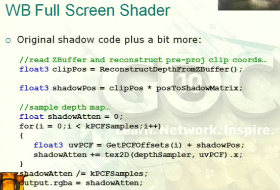
Parallel light sources for all shadows for single matrix multiply with no w divide.
float3 shadowPos = pixelPos * posToShadowMatrix;Holy Grail = 1 filtered texel per pixel
"White Buffer" used to store full screen shadow buffer data for up to 4 lights. Shadow map cascades are no longer sampled in the opaque rendering pass. Renders each cascade's shadow map into the WB. The WB is then sampled once in the opaque pass.

Min blending is used to render the cascades to the WB in an order independent manner.
ZCull Unit is used to minimize the cost of full screen cascade passes. ZCull unit has conservative ZNear and conservative ZFar for "depth bounds test".
 Left: ZNear. Right: ZFar
As the figure below illustrates, we are only interested in the areas of the screen that have depth values which fall within the z near and z far values.

So, the rendering process proceeds (for a 3 cascade shadow) as:
ZPrePass
Cascade 2 Shadow Map
Render Cascade 2 to WB
Cascade 1 Shadow Map
Render Cascade 1 to WB
Cascade 0 Shadow Map
Render Cascade 0 to WB
Opaque
This deferred approach can be used to apply different settings to each cascade. Eg: different sampling quality, different resolutions. It can also be used to tile the cascades and increase the effective resolution of the cascades. For example, we might want to double the effective resolution of cascade 0 (the nearest cascade) by rendering it as 4 x 1024 x 1024 tiles rather than just 1 x 1024 x 1024 tile.
ZPrePassThat is a lot of rendering passes that can only be fast if we apply some aggressive optimizations.
Cascade 2 Shadow Map
Render Cascade 2 to WB
Cascade 1 Shadow Map
Render Cascade 1 to WB
Cascade 0 Shadow Map (TILE 0)
Render Cascade 0 to WB (TILE 0)
Cascade 0 Shadow Map (TILE 1)
Render Cascade 0 to WB (TILE 1)
Cascade 0 Shadow Map (TILE 2)
Render Cascade 0 to WB (TILE 2)
Cascade 0 Shadow Map (TILE 3)
Render Cascade 0 to WB (TILE 3)
Opaque
Using this technique the GOW team could achieve 10 megapixel resolution (approx 3600x2800) shadows for the nearest cascade.
Optimization
In most GOW scenes shadows run at 4-5 ms.
Depth reconstruction has to go away - one pass to make fp32 depth buffer. From 5 cycles to 1 texture read.
Two speed hits for shadows:
1) Rendering casters
2) Full screen passes for receivers
Cull Optimizations
Two reasons why pixel not shadowed:
1) Not in volume made by casters
2) In caster volume but not right receiver type
Receiver type culling & volume culling
Receiver Type Culling
Two kinds of receiver type culling used in GOW:
1) Baked shadow integration. Eg: ground may use baked shadows but there will be a matching hidden caster to cast dynamic shadows on dynamic shadow receivers. Hidden casters are not visible in the world but are only rendered to the cascade shadow map. Hidden casters are rendered in unique shadow map cascades.
ZCull Unit culls stencil too.
- Can cull based on depth independent criteria.
- ZPrepass can lay down scene stencil for free.
- Same reject rate as Z.
Stencil culling is used to mask out baked shadow receivers when rendering the hidden casters.
2) Minor characters cast only on geometry marked as "background". So minor characters are not self casting. The beauty of this is the more background characters there are on screen the fewer pixels are affected by shadows. This optimization appears to make more sense when you have baked shadows.
Volume Culling
CPU based algorithm, GPU results
2D Cells from 3D Cells
No more full screen passes.
CPU processing per 2D cell. We want to know 3 things for every cell:
1) Do we need to draw it?
2) How big does it really need to be?
3) What distance to camera are shadows?
(64 cells 8x8 for GOW)
 One 8x4x8 gridded box per cascade
Casters and receivers in the grid. What casters hit which receivers?
For each caster, the sphere bounds are stretched in the shadow dir to form a capsule. Rather than use a capsule for visibility testing this was converted to a AABB (or parallel projected frustum).
 Side view of the grid showing how z near, z far are determined for a 2D screen cell. Partial use of a cell can also be determined by projecting the bounds to the 2D cell.
Summary
These are some great techniques for achieving high quality shadows. They are more applicable to a game that uses baked environment shadows and uses static environment lighting. For a game with fully dynamic lighting and shadows these techniques may not be as useful.
Tuesday, January 18, 2011
Getting Started with XNA
I've been meaning to mess around with XNA a bit. It looks like a great tool for quickly testing ideas on actual Xbox hardware. Not a big fan of C# though. Here I'll post some of the info and links that I find useful as I get into XNA development.
YouTube - XNA 4.0 Tutorial: Part 1
YouTube - XNA 4.0 Tutorial: Part 1
Monday, January 17, 2011
Back to Basics - SIMD Part II - Intel
Wikipedia covers the basics of Intel's SSE instruction set:
http://en.wikipedia.org/wiki/Streaming_SIMD_Extensions
In 2011, SSE5 will be released and Intel is introducing a new AVX SIMD instruction set featuring 256-bit registers and data paths presumably for double precision float vectors.
When it comes to writing SIMD code, using intrinsics can make programming for these enhanced instruction sets simpler and less error prone than using asm blocks.
http://www.codeproject.com/KB/recipes/sseintro.aspx
Friday, January 14, 2011
Back to Basics - SIMD Part I - IPhone
To start off the Coder Chameleon blog I'd like to spend some time investigating the world of SIMD architectures on the most prevalent hardware architectures and to determine their commonalities and differences. We'll start with the IPhone and survey the major hardware platforms then maybe develop a simple math library utilizing SIMD on each platform.
SIMD on the IPhone
The wikipedia page on IPhone details the evolving hardware architecture of the platform (http://en.wikipedia.org/wiki/IPhone). The original IPhone and IPhone 3G were based on the ARM11 instruction set which had SIMD instructions but it was not until the IPhone 3GS that support for ARM's NEON general purpose SIMD engine was made available.
The IPhone 3GS uses the S5PC100 chip based on the ARM Cortex A8 architecture:

And an excellent presentation on SIMD on IPhone:
Cranking Floating Point Performance to 11 by Noel Llopis
http://www.slideshare.net/llopis/cranking-floating-point-performance-to-11-on-the-iphone-2111775
The presentation above references the vfp math library (by Wolfgang Engel) http://code.google.com/p/vfpmathlibrary.
NEON
Here is an excellent introduction to NEON on the IPhone:
http://wanderingcoder.net/2010/06/02/intro-neon/
- 16 x 128 bit registers named q0 to q15 (q for quadword).
- These registers can also be referenced as 32 x 64 bit double word registers named d0 to d31.
- 'q' means the instruction saturates
- 'r' means the instruction rounds
- 'h' means it halves
APPENDIX I - NEON and VFP References
ARM Info Center: NEON and VFP Programming
http://blogs.arm.com/software-enablement/161-coding-for-neon-part-1-load-and-stores/
http://www.delmarnorth.com/microwave/requirements/TestCodeTutorial_neon-test_draft2.pdf
APPENDIX II - General IPhone Hardware Reference
Wandering Coder - A Few Things IOS Developers Should Know About ARM Architecture
Thursday, January 13, 2011
Welcome to Coder Chameleon.
The purpose of this blog is to track research into various aspects of videogame programming. Graphics, AI, sound, languages, optimization and hardware. The blog is mainly a personal research tool for me to log research notes and references but I hope it will be of some use to others too.
I will try to strike a balance between being comprehensive and concise by eliminating fluff and linking to references for details. I don't have a lot of time to devote to the blog so things may evolve in a slow and unpredictable fashion.
I will try to strike a balance between being comprehensive and concise by eliminating fluff and linking to references for details. I don't have a lot of time to devote to the blog so things may evolve in a slow and unpredictable fashion.
Subscribe to:
Posts (Atom)